

Conductor termination fails more often at the lug than anywhere else in a low- or medium-voltage assembly, and the failure is almost always a selection error made before the crimp. Understanding the types of cable lugs available, and the engineering logic that separates one family from another, is what lets an installer match the connector to the conductor, the stud, and the operating environment instead of defaulting to whatever is in the kit.
What a Cable Lug Is and Where It Is Used
A cable lug terminates a stranded or solid conductor into a connection point: a busbar, a circuit breaker terminal, a grounding stud, a motor lead. It transfers current from a flexible or rigid conductor to a bolted interface while holding the mechanical load that the joint will see over its service life. A correctly specified lug keeps contact resistance low enough that the termination runs no hotter than the conductor it serves. You find them across panel building, switchgear, traction power, photovoltaic strings, UPS banks, and any installation where a conductor has to leave the cable and become a bolted contact.
How Cable Lugs Are Classified
Four parameters define a lug. The palm geometry determines how it meets the terminal: ring, fork, pin, flat tab, or hook. The hole pattern sets the stud size and whether the connection is single- or two-hole, the latter resisting rotation under fault current and vibration. The barrel governs termination method, whether crimp, mechanical screw, or compression. Insulation is the fourth axis, splitting the catalogue into non-insulated terminals and pre-insulated designs with a colour-coded sleeve. Reading a lug against these four axes, rather than by appearance, is what makes cross-referencing between manufacturers reliable.
The Most Common Types of Cable Lugs
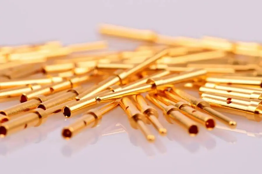
Among the recurring types of cable lugs, the ring terminal dominates wherever a closed, captive connection is required, since it cannot vibrate off a partially loosened stud. Fork and spade terminals trade that security for fast service access on terminal blocks. Round and flat pin terminals feed conductors into clamp-style terminations and connector blocks. Hook terminals suit field-serviceable points under restricted clearance. Pre-insulated ring and fork terminals cover the low cross-section signal and control range, where the integrated sleeve provides strain relief and the colour code confirms conductor size at a glance.
Cable Lug Materials: Copper, Aluminium and Bimetallic
Electrolytic copper remains the reference for conductivity and crimp stability, and tinned copper extends that performance into corrosive, marine, and washdown settings without altering the bolted interface. Aluminium lugs answer weight and cost on large feeders, but an aluminium conductor terminated onto a copper busbar demands a bimetallic transition to suppress galvanic corrosion at the dissimilar-metal junction. Friction-welded bimetallic lugs place an aluminium barrel against a copper palm so the crimp lands on like metal while the bolted face stays copper. Material choice follows the conductor and the environment, never preference.
Choosing Copper Cable Lugs for Reliable Connections
Copper earns its place wherever joint reliability outranks weight: control panels, traction equipment, grounding systems, high-cycle UPS terminations. Sizing starts from the conductor cross-section and class, then accounts for ambient temperature and the stud diameter at the destination. A professional range such as Cembre copper cable lugs spans standard ring terminals, heavy-duty long-neck designs, two-hole and 90° configurations, and fine-stranded variants for class 5 and 6 flexible conductors, each tested against UL 486A-486B and dimensioned to recognised conductor classes. Selecting a lug whose barrel matches the actual conductor class, not just its nominal cross-section, is the single decision that most affects long-term joint integrity. Tinned versions extend the same geometry into corrosive duty without changing the crimp procedure.
How to Size and Crimp a Cable Lug Correctly

A sound termination begins with conductor and barrel agreement: the stripped conductor must fill the barrel without forcing, and the lug must be rated for the conductor class. Die and tool are then matched to the connector, since a crimp formed with the wrong die profile or insufficient compression force will pass a pull test yet drift in resistance under thermal cycling. Hexagonal and indent crimps each have a defined die set; mixing them voids the connection rating. Compression force, die marking, and barrel are read together against the manufacturer’s table before the first crimp, and the finished joint is verified for fill, deformation, and electrical continuity.
Selection Checklist: Matching the Lug to the Job
Specification resolves to a short sequence. Confirm conductor material and class, then cross-section and operating current. Fix the stud diameter and decide single- or two-hole based on vibration and fault exposure. Set the material against the environment, copper or tinned copper for corrosion, bimetallic for aluminium-to-copper transitions. Choose palm geometry from the terminal it meets, and confirm the crimp system and die availability before committing. Each answer narrows the catalogue until one family, and one size, remains.